PART 2: USING THE TOOLS TO CREATE DATA
Before You Start…
To install and use the toolbox, simply move this “CLI Toolbox” folder and its contents to an easy-to-locate directory on your computer (suggestion: C:\CLI_GIS\CLI Toolbox). DO NOT rename, remove, or reorganize any of the files within this folder, as all of the operations are referential. Next, in ArcMap or ArcCatalog, open the ArcToolbox window, right-click on the ArcToolbox, choose Add Toolbox… and navigate to this directory to locate the CLI Toolbox. You may also run tools by finding the CLI Toolbox in the ArcCatalog window in ArcMap.
Here are a few important notes regarding the general use of tools in ArcGIS.
- You can run tools from either ArcMap or ArcCatalog, though some of the CLI tools that deal specifically with editing or displaying features must be run from ArcMap, and the tools that access and summarize the CR Enterprise database must be run from the CR Enterprise Access map document.
- By right-clicking on a tool in the toolbox, you can run it in batch mode. This could be useful for importing multiple datasets to a scratch geodatabase (PAGE NO p. 11), making multiple spreadsheet summaries (PAGE NO p. 25-27), or making Google Earth versions of more than one geodatabase (PAGE NO p. 25).
- When viewing a tool dialog box, always use the Show Help >> button to get the extra help that is written into the interface. Information about a specific parameter will be shown when the cursor is in that parameter. A lot of usage questions can be answered by reading this information. You can also right-click on the tool to view its Item Description or use the Tool Help button to see all of the help documentation at once.
- The Results window (found under the Geoprocessing menu) logs all the information generated from each attempt to run a tool. If you’d like to rerun an operation with all or most of the same parameter values as were previously entered, just double click the instance log of the tool in the Results window, and the dialog box will reopen with all the parameters filled as they were at the time that the tool was run. This is extremely useful. Further note: As the Results window fills up with tool logs, the map document will take longer and longer to save. Remove these logs to decrease the save time of a map document.
- The ESRI help menu is extremely useful, and will answer a lot of general questions. It can be opened from the main Help menu in ArcMap or ArcCatalog.
Creating Project Folders
The easiest way to begin creating data for a new landscape is to use the Create New Project Folder tool.
- Open the Create New Project Folder tool from ArcMap or ArcCatalog
- Enter the Region Code, Alpha Code and CLI Number for the landscape (see Figure 5).
- Be sure to enter the Alpha Code and CLI Number correctly, as they will not be checked against any existing lists of parks or landscapes.
- Click OK to run the process.

This will create a new folder named by the landscape number and embedded in the preferred directory structure. This folder will contain a new scratch geodatabase and map document, both named with the CLI number.
The map document and scratch geodatabase templates that are used in this process are located in the bin folder (CLI Toolbox\scripts\clitools\bin). If desired, modifications can be made to the map document template and they will be present in all future project folders. For example, one may want to have a layer of counties or an imagery basemap present in each new map document. Just locate the “mxd_template.mxd” in the bin folder, add the desired layers to it, and save it. At present, the NPS boundary layer is in the map document template, as well as each of the scratch feature classes from the accompanying scratch gdb. (Warning: Do not remove the NPS boundary layer from the template map document. This will cause an error when the tool tries to zoom to the Alpha Code that has been entered.)
Importing Existing Spatial Data
The Import to Scratch GDB tool is the best way to prepare an existing dataset for inclusion in a CLI Standards geodatabase. Or, more generally, it’s a good way to add and populate all of the standards-compliant fields.
- Open the Import to Scratch GDB tool from ArcMap or ArcCatalog
- Locate the dataset (e.g. a feature class or shapefile) to be imported to a scratch geodatabase. In fact, any geodatabase can work as the target; a scratch geodatabase is not required.
- Enter values for any fields that you’d like to batch-populate during the process.
- See the tool dialog help for more information on each parameter.
- Click OK to run the process.
When a feature class or shapefile is imported with this tool, a copy of the dataset is made in the target geodatabase and all of the CLI standards fields are added to it, while all of its original fields and attributes are retained. The original dataset itself is unaltered.
In addition to the CLI standards fields, the “fclass” field is also added. As explained in more detail later (see p. ???), if features are to be taken from this imported feature class to a CLI Standards geodatabase using the Sort Scratch to Standards tool, they must have a value in the “fclass” field.
See Figure 6 for an illustration of how a dataset is processed through this tool.

Creating Data with Scratch Feature Classes
Creating new data can be thought of as a two-step process: making geometry, and updating fields. The scratch feature classes are designed to make these processes very easy.
--CREATING GEOMETRY--
While creating geometry for features, only two fields need to be filled out each time a feature is created: the CLI_ID and “fclass” fields. All other fields can be batch-populated later. To digitize features from an aerial, add an imagery basemap, begin an edit session in the scratch geodatabase, and draft features in the point, line, or polygon feature class.
Here are a few tools from the editing toolset that are useful for this process:
- In the Editing Tools > Spatial Reference toolset, you can quickly set the coordinate system of the data frame. It is recommended to use a projected coordinate system (UTM or State Plane) when digitizing features that have right angles, like buildings. You can then use the Rectangle in the Create Features window, or the ctrl + E constrain perpendicular shortcut (use the ArcMap help for an extensive list of editing keyboard shortcuts).
- The Generate Centroids tool will take input features from a line or polygon feature class and place centroids for them in the corresponding point feature class. The tool should be run after the “fclass” and
CLI_IDhave been entered, to eliminate the need to reenter those values in the new centroid features. Certain fields will be filled in during this process, e.g. theBND_TYPEof the new centroid is automatically set to “Derived point”. - If you are editing a CLI Standards geodatabase that contains multiple landscapes, use the Zoom To Unit tool to move from one landscape to the next. However, the zoom won’t work correctly if there are features selected when it is run.
In addition to digitizing (drawing) new data, feature geometry can also be copied and pasted from existing datasets into the scratch feature classes. CAUTION: copying features from a feature class that has an undefined coordinate system will lead you down a dark and mirthless road. Be sure to define the correct coordinate system for any dataset you are using.
Use these steps to copy and paste features:
- In ArcMap, add the source and target datasets to the table of contents.
- Start an Edit session in the scratch geodatabase.
- Select only the features that you wish to copy from the source dataset.
- Right-click in the data frame (you must be in Data View) and select Copy.
- Right-click in the data frame again and select Paste.
- Select the scratch feature class into which you’d like to paste the features.
This can be a very slick process, because it is an Append operation with the schema type set to “NO_TEST”. This means that any fields that are common between the original and the target will have their values transferred.
To take this concept further, consider the following example of how it can be used to get geometry from a single imported feature class into many different scratch geodatabases, i.e. many different landscapes.
- Create a blank geodatabase in the alpha code folder, for example, C:\CLI_GIS\Midwest Region\SLBE\empty.gdb
- If you have a dataset that will be used in all of the landscapes in SBLE, say trails.shp use Import to Scratch GDB to import this dataset into the new empty.gdb, instead of importing it to an individual scratch geodatabase. The result will be a feature class called imp_trails.
- Add imp_trails as a layer in all of the landscape map documents for SLBE, and, using the process described above, copy and paste features from imp_trails into the scratch feature classes for that landscape.
- Only update the
CLI_IDand “fclass” values once the feature has been pasted into the scratch feature class. - Now, your scratch feature classes will have a combination of newly digitized features (from you) and imported features (copied from imp_buildings), while the original imp_buildings feature class remains unaltered.
--UPDATING FIELDS--
Once you have geometry for all of your features, and they all have a CLI_ID and an “fclass” value, you can use Update Fields in Selected Records to batch populate (almost!) all of the remaining fields. Simply select all of the features you wish to update, enter information in the tool dialog for whatever fields you’d like to fill out, and run the tool. There are a number of special methods within the dialog box that allow for quick ways to fill the parameters, all of which are documented within the tool dialog itself. One of these features that deserves explanation here is the “Get CLI Info from Table” checkbox. If this box is checked, all of the CLI-related fields will be updated for each feature based on its CLI_ID. The fields that are updated are:
CLI_NUM(number for landscape that the feature is in)LAND_CHAR(the feature’s landscape characteristic category)RESNAME(feature name)CONTRIBRES(contributing status)ALPHA_CODE(alpha code for park location of feature)UNIT(name of park)REGION_CODE(name of region)UNIT_TYPE(type of park)
All of this information is pulled from the CLI Lookup Tables that are described on PAGE NO p. 7. Filling these fields with this method ensures that the GIS data is a direct reflection of the CLI.
Recommended use for Update Fields in Selected Records:
- Draft (or copy/paste) all feature geometry
- Be sure a
CLI_IDand “fclass” value has been entered for each feature - Select ALL features and run tool with only the “Get CLI Info from Table?” box checked
- Unselect all features and reselect any that were digitized using the same source data (aerial imagery, e.g.) and rerun tool, filling out all source/creation info parameters that apply to each selected feature.
- Take care that the “Overwrite existing values?” box is used appropriately.
Tip: Start an Edit session for the feature classes whose values you are updating, and if a mistake is made, use the Undo function from the main Edit menu to reset the field values (you will not be able to undo operations if there is no current edit session).
Further notes on the Update Fields in Selected Records tool:
- There cannot be layers present in the table of contents that have the same name. This is a shortcoming, but simply renaming the offending layers in the table of contents will fix it.
- The tool can be used on any feature class in any geodatabase. If any fields from the input parameters don’t exist in the feature class, they will be skipped without issue.
- To get the most out of this tool and the advanced functions available in the tool dialog, read the help for each parameter. There are some very significant shortcuts written into the tool dialog.

****Migrating Features from Scratch to Standards****
All of the above steps are geared toward creating a set of features in a scratch geodatabase—either in the scratch feature classes or in imported feature classes—that have AT LEAST the CLI_ID and “fclass” field filled out. Ideally, they will have all fields filled out at this point. The next step is to sort these features into a CLI Standards geodatabase based on the “fclass” value. This process is illustrated below, and it should further demonstrate the intention behind the implementation of the scratch geodatabase.
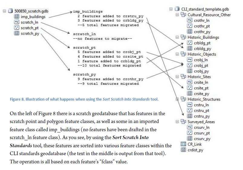
If the Sort Scratch Into Standards tool is run and a feature does not have a value in the “fclass” field, that feature will be ignored during the operation. This is essential because, referring to the example above, there may be hundreds of buildings in the imported buildings feature class (imp_buildings), but only five of them were buildings in this landscape, so only five were assigned “fclass” values (three values were “crbldg_py” and two were “crstru_py”). This is a good example of the ease with which the user is able to split features in the same imported feature class into multiple standards feature classes. This may not be necessary if you have a single GPS file for one feature, but it is in cases where a dataset covers a large geographic area or large variety of feature types.
If the data import, creation, and field population steps are all followed as described above, the result of this sorting operation will be a CLI Standards geodatabase with the features from the scratch geodatabase sorted into the correct feature classes. However, there are a few more steps necessary to complete the CLI Standards geodatabase.
Steps for using Sort Scratch Into Standards
- Open the Sort Scratch Into Standards tool from ArcMap or ArcCatalog.
- Locate the scratch geodatabase (e.g. a feature class or shapefile) that contains feature classes with features to sort.
- Select which feature classes have features that should be sorted to the new CLI Standard geodatabase.
- If the features should be added to an existing CLI Standard geodatabase (for example, a regional geodatabase), enter this geodatabase as the target.
- If no target is provided, a new CLI Standard geodatabase will be created which contains only the newly sorted data. (This can later be incorporated into a regional or park geodatabase using the Merge Standards GDBs tool.)
- Click OK to run the process.
Completing the CLI Standards Geodatabase
Once features have been sorted into a CLI Standards geodatabase, there are a few final steps before that geodatabase is fully ready for analysis and upload to the CR Enterprise database, or for aggregation with other CLI Standards geodatabases. Follow the numbered steps below, and read past them for a more detailed description of the tools and processes involved.
- Finalize all geometry:
- Use Zoom To Unit to move between various landscapes
- Use Generate Centroids for any polygons representing buildings or structures
- Make any necessary modifications to geometry of existing features
- Finalize all fields:
- Use the Check Mandatory Fields to make sure there are no Null values in the required fields (disregard GUIDs)
- Use Update Fields in Selected Records to batch update data creation or source information if missing
- Use Check Values Against Domains to make sure all attributes meet the standards domain values
- Use the Fix Field in GDB tool to standardize attributes across all feature classes
- Use Create GUIDs to create GUIDs for all features in the geodatabase (do not overwrite GUIDs)
- Use Sync CR Link and Catalog Tables to populate and consolidate the CR Link and CR Catalog tables
- During Sync CR Link and Catalog Tables, an error log will be created with if a
CR_IDhas conflicting program IDs. If this is the case, rerun the tool once. If the errors persist, follow these steps:- Make sure entire geodatabase is visible in data frame
- Use the Find function (look for IMAGE??? in the Tools toolbar) with problematic
CR_IDs from log to locate the conflicting spatial data - Use ctrl + F in the CR Link table to find problematic
CR_IDs and associated program IDs - Make sure that the
CR_IDin the CR Link table has the correct program ID. - As necessary, calculate new
CR_IDs for specific spatial features (see below)
- If any changes are made, rerun Create GUIDs (to ensure correctly transferred CR_IDs for multiple geometry features) and then rerun Sync CR Link and Catalog Tables.
- During Sync CR Link and Catalog Tables, an error log will be created with if a
- Check that the CR Catalog and CR Link are in conchordance
- Add the two tables to the table of contents, and open them.
- Select all rows in the CR Catalog
- Use the relationship class (IMAGE???) with the CR Link table to select corresponding
CR_IDs in the CR Link. - If all rows are not selected in the CR Link table, redo steps 3 and 4 above until they are.

By following all of these steps, the user should produce a cohesive CLI Standard geodatabase. Read on for more background and information on how the tools and processes described above are carried out.
--FIELD VALUES QA/QC--
There are three tools in the Standards GDB > Maintenance toolset that will assist with overall analysis and correction of the attribute values that have been entered (or left out) thus far. Their use is fairly straight-forward, so here is a quick description of each one:
- Check Mandatory Fields – Analyzes all of the CR Spatial Data Transfer Standards required fields and return a list of all the feature classes in the geodatabase and the fields in each feature class that have empty or Null values. Can be used on any file geodatabase. You can use this list to inspect the attribute table of each feature class to make the necessary corrections. Tip: When you have opened an attribute table and need to know where the Null or empty values are in a given field, just double-click on the field header and the table will be sorted based on that field, with Null or empty values on top.
- Check Values Against Domains – This tool can be used on any geodatabase; it is not restricted to CLI Standards or Scratch geodatabases. It makes lists of all the domains that are present in the geodatabase and then iterates through every field that has been assigned to a domain. All of the field’s values are checked against those in the appropriate domain. For example, in the
MAP_METHODfield, there could be the “HDIG” value (for “heads-up digitized”), but this will be flagged because “HDIG” is not inMAP_METHODdomain. This tool will return a list of all feature classes, and any values within those feature classes that don’t match the domain for the field they are in. Findings from this tool may be easily corrected with the following tool.- Note 1: Not all fields that have domains are required by the Spatial Data Transfer Standards.
- Note 2: The domain for the
LAND_CHARfield does not carry variations on the normal values with different cases. For example, it contains “Buildings and Structures” but not “Buildings And Structures”. However, the CLI itself does contain both, which means that both will be found in the spatial data. Therefore you may find instances where theLAND_CHARhas values that are not in the domain. All tools in this toolbox are written to disregard the case ofLAND_CHARvalues, so “Buildings And Structures” is not a problem at all and need not be corrected. - Note 3: Similar to the
LAND_CHARdomain, any domain that concerns park type or alpha code should not be considered an authoritative list of all possible park types or alpha codes. So there may be values for those fields that are completely acceptable, but not in the domain.
- Fix Field in GDB – This tool can be used on any geodatabase; it is not restricted to CLI Standards or Scratch geodatabases. When a geodatabase is entered into the first parameter, it will create a list of all the fields that exist anywhere in that geodatabase. When one of these fields is selected, it will generate a list of all the unique values that exist in that field. You then have the opportunity to select any number of the existing values, and enter a new value that should replace all of these old values. For example, you would use this tool to change all occurrences of “HDIG”, “digitized”, or “Digitised” to the standards-compliant value “Digitized”.
--CREATING GUIDS--
Use the Create GUIDs tool to create the CR_IDs and GEOM_IDs for all features in the CLI Standards geodatabase. You may wish to only create GUIDs for features in a certain landscape or park that exist within the geodatabase. To do this, enter a CLI Number or Alpha Code in the tool dialog. You can create only CR_IDs or only GEOM_IDs with the tool, but it generally makes sense to always create both. It is not advisable to overwrite existing GUIDs, but there may be circumstances in which this is necessary.
When this tool is run, the first half of its operation is to simply calculate new GUIDs. After this is done, and if CR_IDs have been created, it will continue to transfer CR_IDs from one feature to another wherever there is multiple geometry representing a single physical feature (refer to the document “Graphical Explanation of GUIDs” for a clear explanation of how overlapping CR_IDs work). During this process, CR_IDs are transferred for any features that:
- are within the same feature class dataset (i.e. are both considered Historic Structures)
- overlap each other
- have matching
CLI_IDs (meaning they represent the same feature)
CR_IDs are transferred from polygons to lines and polygons to points where polygon features are present, and from lines to points where no polygons are present.
Running the Create GUIDs tool can take up to an hour for an entire region if CR_IDs are created (which causes the transfer process to occur), depending on how many multiple geometry features there are.
--SYNCHRONIZING THE CR LINK AND CR CATALOG TABLES--
Pulling information from the spatial data to create and populate the CR Link and CR Catalog tables is done with the Sync CR Link and CR Catalog Tables tool. It is important to run this tool last, though it can be run as many times as necessary—to ensure that these tables reflect not only the current spatial records and GUIDs—but also the current qualitative information attached to each feature (LAND_CHAR, ALPHA_CODE, etc.).
When the tool is run, first, the CR Catalog is created/updated and all relevant information from all of the features in the feature classes is written to it. The CR Catalog has one row per GEOM_ID, which means that because every spatial feature has a unique GEOM_ID, there will be a row in the CR Catalog for every single spatial feature in the geodatabase.
Second, the CR Link table is created/updated and all of the unique CR_IDs are written to it. The CR Link table has one row per CR_ID, which means that there is a row for each physically distinct feature in the geodatabase. The other characteristic of the CR Link table is that it contains program IDs (NRIS_ID, LCS_ID, ASMIS_ID, CLI_ID, FMSS_ID etc.) for each physical feature that is represented in the geodatabase. Apart from the CLI_ID, this information is not stored in the spatial features, which means that unlike the CR Catalog, the CR Link table cannot be recreated from scratch every time the tool is run, because if it were, any program IDs that were already in it would be lost.
To deal with this, the synchronization of the CR Link table is really a 3-step process:
- All of the features from all of the feature classes are appended to the existing CR Link table. That way, if you have entered numbers in the
FMSS_IDfield of, say, the Historic Buildings point feature class, all of theseFMSS_IDs will be transferred along in to the CR Link table. - The tool runs through every row in the now-inflated CR Link table, and begins an in-memory list of all unique
CR_IDs. During this iteration, if aCR_IDis encountered that already exists in the rapidly growing list, each of the program IDs that are attached to these identicalCR_IDs are combined. This means that if oneCR_IDhad only been assigned aCLI_ID, and another instance of the sameCR_IDonly has anFMSS_ID, these values will be combined into a single line of the CR Link table. IMPORTANT NOTE: It may happen that two conflicting database IDs have been entered for the sameCR ID, say, twoCLI_IDs for the same house. The tool will pick one of these IDs, and record the error in a log. You must adjust the table or spatial data manually at this point to correct the error, and then rerun the tool. See the tool messages/documentation and the steps on PAGE NO page 18 for a more thorough explanation of this process. - Finally, the CR Link table is rewritten with all of the unique
CR_IDs and their respective combined program IDs.
Running the Sync CR Link and Catalog Tables tool can take up to 15 minutes for an entire region.
Adding Program IDs to the CR Link Table
Chronologically, it doesn’t matter when the user chooses to add program IDs to the CR Link table, however there is no CR Link table without CR_IDs, so if brand new data is being created, the best practice would be to follow the steps above to create GUIDs and synchronize the tables before proceeding.
Program IDs can be added to the CR Link table it two basic ways:
- By directly entering the ID in the correct row of the CR Link table
- Select the feature to which you’d like to add an ID.
- Open the attribute table for the feature class (right-click in the table of contents, choose Open Attribute Table)
- Use the relationship class IMAGE??? with the CR Link table to select the corresponding row in the CR Link table for that selected feature. This relationship class is based on the
CR_ID. - You should now be looking at a single selected row in the CR Link table. Find the appropriate field, and enter the program ID. (Use ctrl + shift + E to start an Edit session if desired, or use Field Calculator.)
- By entering the ID into a matching field in the feature class attribute table and then running the Sync CR Link and Catalog Tables tool to pull the new ID into the CR Link table.
- Select the feature to which you’d like to add an ID.
- Open the attribute table for the feature class (right-click in the table of contents, choose Open Attribute Table)
- Make sure there is a field to hold the new ID that you want to add (
LCS_IDandFMSS_IDfields are already present). The name of this field must be identical to the corresponding field in the CR Link table. - Enter the program ID. (Use ctrl + shift + E to start an Edit session if necessary, or use Field Calculator.)
- Save edits and close Edit session if necessary, and run the Sync CR Link and Catalog Tables tool on the geodatabase, and the CR Link table will be updated accordingly.
A third, more powerful way to batch update program IDs would use a table that can be temporarily joined to the CR Link table and have its values transferred to the CR Link table. An example of this use would be to have a table (*.dbf, *.csv, *.xls, geodatabase table, etc.) that lists FMSS_IDs in one column, and corresponding LCS_IDs in another. The user would join this table to the CR Link table by linking the LCS_ID fields, and then use field calculator on the CR Link FMSS_ID field to transfer all of the FMSS_IDs from the other table.
It’s important to realize that if the Display Geodatabase tool is used to show features that have been assigned an FMSS_ID, for example, the feature must have the FMSS_ID in the CR Link table for it to register. Program IDs entered directly into the feature class attribute table will be ignored by that tool, unless the Sync CR Link and Catalog Tables tool has been run to pull the IDs into CR Link table.